创建自定义材质
 As already mentioned, it is the shader code that is the basis of materials, which actually draws them, taking into account the given parameters, states, textures, etc. And for a long time, programming skills were required to create your own materials.正如前文所述,着色器代码才是材质的核心基础:它根据给定的参数、状态、纹理等要素实际绘制出材质效果。长期以来,创建自定义材质都需要编程技能。
UNIGINE has a visual Material Editor — a powerful tool for 3D artists, which not only saves them from the necessity to know how to write code, but also makes working with materials more convenient. And the result is visible immediately when making any changes and saving the graph, which greatly speeds up iterative development. Most operations are performed by simply connecting different nodes into a graph. The graph can be used to quickly prototype and create complex materials, as well as various special effects for surfaces and objects.UNIGINE配备了可视化材质编辑器(Material Editor),这款强大工具不仅让3D美术师免于编写代码,还大幅提升了材质编辑的便捷性。任何修改在保存节点图后都能即时呈现效果,极大加速了迭代开发流程。大多数操作只需通过连接不同节点即可完成,该节点图能快速实现复杂材质原型设计,以及为表面和物体创建各类特效。
Key features:核心特性:
- Loops are a complex but very cool feature that allows repeating arbitrary sequences of actions many times. We have developed our own implementation of loops in graph, which is almost as good as loops written in code, but much easier to use.循环结构(Loops):虽然复杂但极其强大的功能,可多次重复任意操作序列。我们自主研发的图形化循环实现方案,其功能几乎媲美代码编写的循环,但操作门槛显著降低。
- Portals help to avoid visual noise in complex graphs by hiding a web created by numerous edges.传送门(Portals):通过隐藏大量连线形成的网状结构,避免复杂节点图的视觉混乱。
- Connectors are a special "collapsed" mode of a node, so that it takes up much less space and can be connected to another node in the graph.连接器(Connectors):节点的特殊"折叠"模式,大幅节省空间并保持与其他节点的连接能力。
- Expressions are used for simple mathematical operations, but much more importantly, they can also be used as swizzles for sampling or changing the number or order of components.表达式(Expressions):除处理基础数学运算外,更关键的是能作为通道调配器(swizzles),用于采样或改变组件数量与顺序。
- Subgraphs are created by combining graph fragments and can be used in other materials. It is important to note here that any change to a subgraph is automatically propagated to all graphs where it has been used.子图(Subgraphs):通过组合节点图片段创建,可跨材质复用。需特别注意:子图的任何修改都会自动同步到所有引用它的节点图中。
Working with Material Editor材质编辑器操作指南#
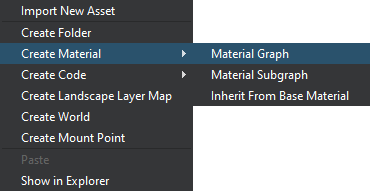
Let's create a new material graph by right-clicking in the Asset Browser and selecting Create Material → Material Graph in the context menu.在资源浏览器右键点击,选择 Create Material → Material Graph,即可新建材质节点图。
The *.mgraph asset represents both the base material graph (which can be edited using the material editor) and a regular base material — the result of graph compilation — you can assign it to objects in the scene or inherit from it a whole hierarchy of child materials without having to rebuild the graph again. Double-clicking on such an asset will open the Material Editor: *.mgraph资源文件同时包含可编辑的基础材质节点图(通过材质编辑器修改)和编译生成的常规基础材质(可直接分配给场景物体,或派生子材质层级体系)。双击该资源将打开材质编辑器窗口:
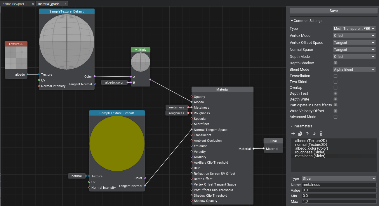
The Material Editor window includes the material graph itself and the Settings panel. The material type determines to what type of node the material can be applied (meshes, decals, or post effects), at what stage of frame rendering the surfaces with this material assigned will be rendered, and the set of supported features and parameters:材质编辑器窗口,包含材质节点图编辑区和设置面板。材质类型决定适用节点类型(网格/贴花/后期特效),渲染阶段,支持的功能参数集:
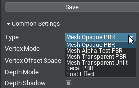
Other settings allow selecting the basis space to be used, activating various features such as emission, tessellation, and controlling the shader compilation settings. 其他设置包括基础空间坐标系,功能开关(自发光/曲面细分等),着色器编译参数。
Nodes and Ports节点与端口#
A material graph consists of nodes — functional blocks responsible for processing input data and connected to each other using edges. By assembling the graph and applying different math, we define the appearance of the material. The Save button saves the graph and compiles it into a material.材质节点图由节点构成:这些功能块负责处理输入数据,并通过边相互连接。通过组装节点图并应用不同的数学运算,我们定义材质的外观。保存按钮会保存节点图并将其编译成材质。
The Material node is the main node of your material. It provides a set of input graph data and generates a material of a certain type depending on the current settings.Material(材质)节点是材质的主要节点。它提供一组输入图数据,并根据当前设置生成特定类型的材质。
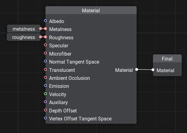
For example, for PBR materials we can control Albedo, Metalness, Roughness, Specular, Microfiber, and Normal values that define the surface properties.例如,对于PBR材质,我们可以控制反照率(Albedo)、金属度(Metalness)、粗糙度(Roughness)、高光(Specular)、微纤维(Microfiber)和法线(Normal)等定义表面属性的值。
The Material node output is connected with the Final node, which is the main node of the output material.Material(材质)节点的输出与Final(最终)节点相连,这是输出材质的主要节点。
A material graph can contain several Material nodes, but only the one connected to the Final node will be used.一个材质节点图可以包含多个Material(材质)节点,但只有连接到Final(最终)节点的那个会被使用。Nodes have ports to connect to each other and transfer data, they define the input (left side) or output (right side). Connecting edges to the ports ensures that data is transferred through the material graph node network and processed.节点具有用于相互连接和传输数据的端口,它们定义了输入(左侧)或输出(右侧)。将边连接到端口可确保数据通过材质节点图网络传输和处理。
Each port has a data type that defines the edges that can be connected to it (float, float4, matrix, texture, etc.). There is an automatic type conversion for convenience.每个端口都有一个数据类型,定义可以连接到它的边(float、float4、matrix、texture等)。为了方便起见,提供自动类型转换。
A quick chart on data types and their indications:数据类型及其表示法的快速图表:
 float
float |
 float2
 |
 float3
 |
 float4
 |
 int
int |
 int2
int2 |
 int3
int3 |
 int4
int4 |
 matrix — a matrix of float values: float2×2, float3×3, float4×4.
matrix:浮点值的矩阵 float2×2、float3×3、float4×4
matrix — a matrix of float values: float2×2, float3×3, float4×4.
matrix:浮点值的矩阵 float2×2、float3×3、float4×4 |
|||
 texture — any type of a texture: Texture 2D, Texture 3D, Texture 2D Array, Texture 2D Int and Texture Cube.
texture:任何类型的纹理:Texture 2D、Texture 3D、Texture 2D Array、Texture 2D Int、Texture Cube
texture — any type of a texture: Texture 2D, Texture 3D, Texture 2D Array, Texture 2D Int and Texture Cube.
texture:任何类型的纹理:Texture 2D、Texture 3D、Texture 2D Array、Texture 2D Int、Texture Cube |
|||
 bool — a boolean value used in logical nodes and loops.
bool:布尔值,用于逻辑节点和循环(loops)
bool — a boolean value used in logical nodes and loops.
bool:布尔值,用于逻辑节点和循环(loops) |
|||
 any — arbitrary data type meaning the port supports several data types.
any:任意数据类型,表示端口支持多种数据类型
any — arbitrary data type meaning the port supports several data types.
any:任意数据类型,表示端口支持多种数据类型 |
|||
 error — indicates an error (e.g., no required input provided or type conversion has failed).
error:表示错误(例如,未提供所需的输入或类型转换失败)
error — indicates an error (e.g., no required input provided or type conversion has failed).
error:表示错误(例如,未提供所需的输入或类型转换失败) |
|||
Only one edge can be connected to any input port, but you can connect multiple edges to an output port.任何输入端口只能连接一条边,但可以连接多条边到输出端口。
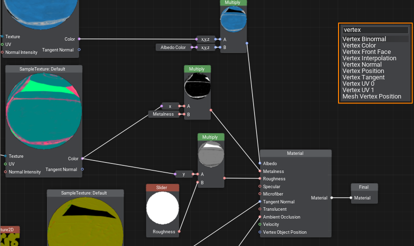
Ports have adapters that allow you to select data components in any order, combine, and reorder them, providing easy access to elements and more flexibility, thus minimizing unnecessary graph complexity.端口具有适配器,允许你以任何顺序选择、组合和重新排序数据组件,提供对元素的轻松访问和更大的灵活性,从而最大限度地减少不必要的图复杂性。
Example: we can choose which 3 components of albedo_color (float4) will be used as float3.示例:我们可以选择albedo_color(float4)的哪3个组件用作float3。
Adding New Nodes添加新节点#
To add a new node, right-click on the background or press the Space button and select the node type from the palette, or type its name in the search field.要添加新节点,请右键点击空白处或按空格键,从选项板中选择节点类型,或在搜索字段中输入节点名称。
Dragging an edge from an input port opens a node creation palette with a pre-set filter to the required data type for the corresponding port.从输入端口拖拽连接线时,将打开节点创建选项板,并自动筛选出与该端口所需数据类型匹配的节点。
Note: using Ctrl+C and Ctrl+V you can not only copy entire graphs within one material or from other materials, but also share them with other developers, because graphs are copied in text format. It is enough to copy the resulting text and paste it into the Material Editor window to get a ready graph.注意:使用 Ctrl+C 和 Ctrl+V 不仅可以复制同一材质内的节点图,还能跨材质复制或与其他开发者共享,因为节点图以文本格式复制。只需复制生成的文本并粘贴到材质编辑器窗口,即可获得完整的节点图。
Textures can be dragged directly from the Asset Browser. In this case, a Sample Texture node with corresponding settings will be added automatically.纹理资源可直接从资源浏览器拖拽添加。此时系统会自动创建带有相应设置的 Sample Texture(采样纹理)节点。
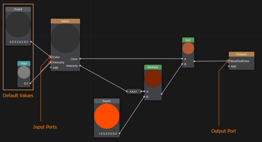
Parameters参数设置#
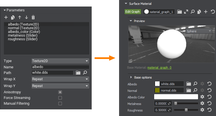
To make values available for further editing, you should explicitly define material parameters by specifying their type, default value, and other options. They can be grouped for convenience.要使参数值可供后续编辑,需明确定义材质参数,包括指定参数类型、默认值等选项。参数可分组管理以便操作。
It is enough to drag a parameter into a graph to use it as a node.将参数拖入节点图即可作为节点使用。
Errors and Warnings错误与警告#
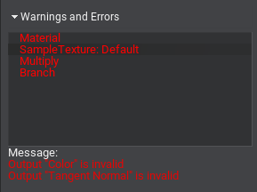
If the built graph has any issues, you will see the Warnings and Errors block in the Settings panel: select an element in the list to learn the details and find the node in the graph that causes an issue, then try to fix it.当构建的节点图存在问题时,设置面板会显示 Warnings and Errors(警告与错误)区块:选择列表中的条目可查看详情并定位问题节点,随后进行修正。
Organizing Graphs组织节点图#
Sometimes, especially in graphs of complex materials, too many intersecting edges make the workspace look like a web and the data flow is incomprehensible. Therefore, it is very important to learn how to organize graphs to improve the perception and simplify the work with them.当处理复杂材质时,节点图中过多的交叉连线会使工作区变得像蜘蛛网般杂乱,导致数据流向难以理解。因此,掌握组织节点图的技巧对提升可读性和简化工作流程至关重要。
UNIGINE 2 has several tools in Material Editor for this purpose: loops, portals, and subgraphs. Let's review each of them in detail.UNIGINE 2的材质编辑器为此提供了多种工具:循环结构、传送门和子图。让我们逐一详解这些功能。
Loops循环结构(Loops)#
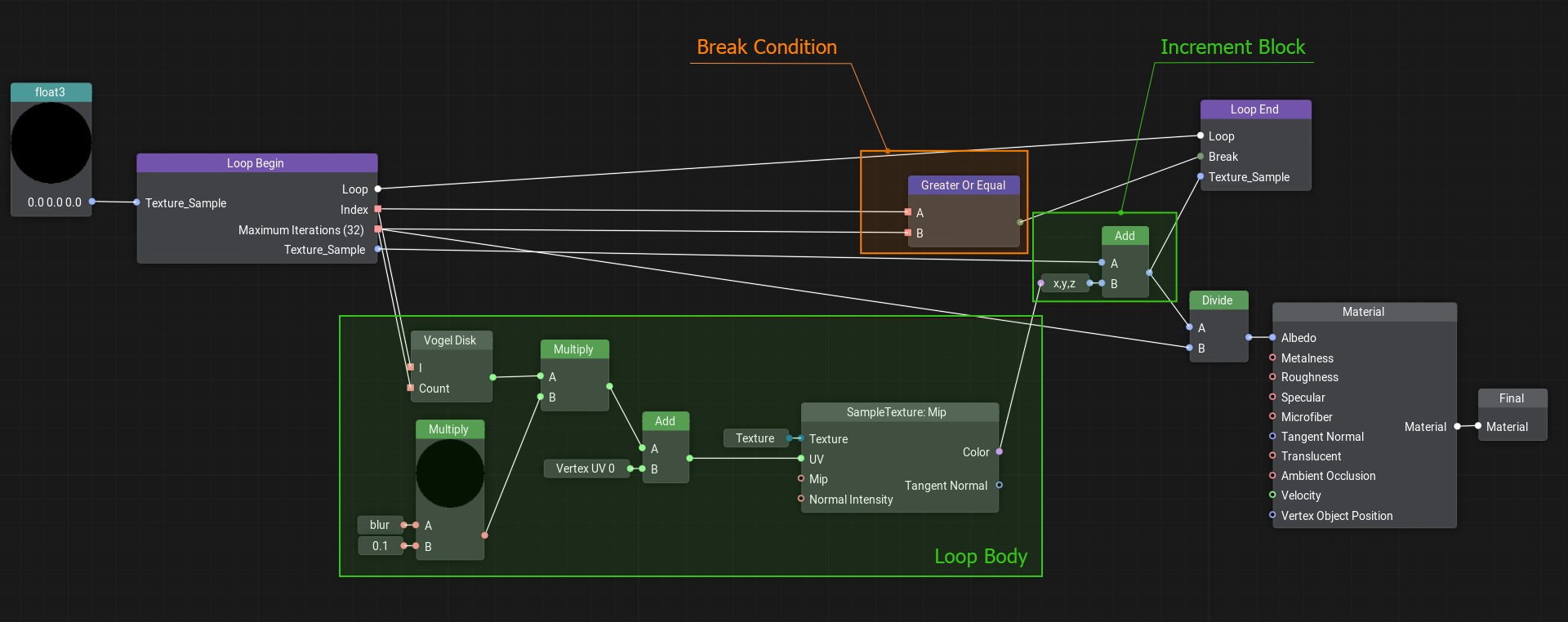
When you need to perform a certain action several times, cloning the corresponding group of nodes will quickly make your graph overcomplicated, even if only 10 iterations are required. In UNIGINE, you can create loops for this purpose, just like in programming.当需要重复执行特定操作时,单纯克隆节点组会使图表迅速变得复杂,即使只需10次迭代。UNIGINE支持像编程语言那样创建循环结构。
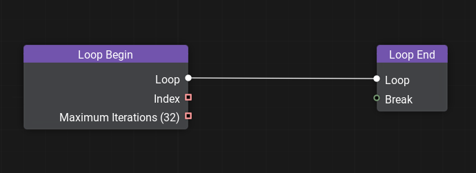
To create a loop, simply add the Loop Begin and Loop End nodes and connect their Loop ports.创建循环只需添加Loop Begin(循环开始)和Loop End(循环结束)节点,并连接它们的Loop(循环)端口。
Double-click on the Loop Begin node to open the loop constructor window and set the variables that change with each iteration of the loop and the total number of iterations. See the documentation for details on creating loops.双击Loop Begin(循环开始)节点可打开循环构造器窗口,设置每次迭代变化的变量及总迭代次数(具体操作详见文档)。
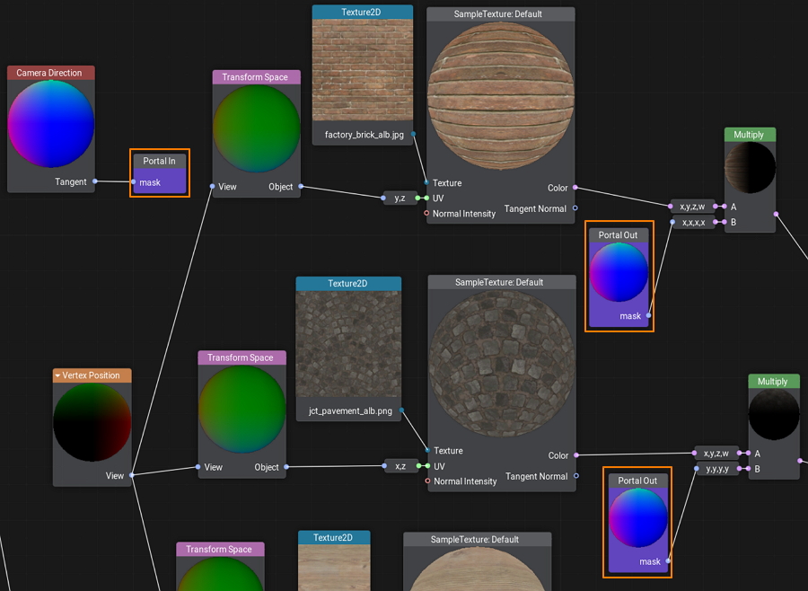
Portals传送门#
A portal is a set of special nodes that has one input (Portal In) and one or more outputs (Portal Out) all having the same name. Portals serve to reduce the number of intersecting edges and make the graph more 'readable'.传送门是一组特殊节点,包含一个输入端口:Portal In(入口传送门)和多个同名输出端口:Portal Out(出口传送门)。它们能有效减少交叉连线数量,显著提升节点图可读性。
Subgraphs子图#
A subgraph is a special type of material graph that can be referenced from inside other material graphs. This can be very useful when the same operation is to be performed multiple times in a single graph or across multiple graphs.子图是一种特殊材质节点图,可被其他材质节点图引用。当需要在单个图表或多个图表中重复相同操作时,这项功能尤为实用。
You simply pack these operations into a box with a set of inputs and outputs and then use this box anywhere you need.你只需将这些操作打包成带输入输出接口的模块,即可随处调用。
Custom Code自定义代码#
No matter how advanced the material system is, sometimes it can be faster to write a few lines of code for math operations than to create a bunch of nodes and connect them. There is an easy solution — create a Function node and wrap any shader function in it. The input and output ports for the node will be generated automatically according to the function signature.即使最先进的材质系统,有时编写几行数学运算代码也比创建大量连接节点更高效。解决方案很简单:创建Function(函数)节点并封装任意着色器函数。节点输入输出端口会根据函数签名自动生成。
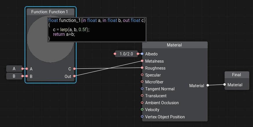
To add or edit code in the node, double-click the node and the code editor window will open. You can write as many functions as you need, the last function in the code will be considered the main function.双击节点可打开代码编辑器进行编写。你可以定义多个函数,代码中的最后一个函数将被视为主函数。
Creating a Material in Material Editor在材质编辑器中创建材质#
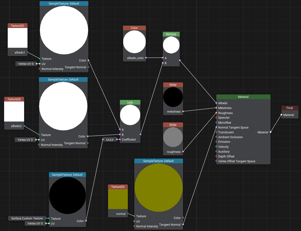
Let's create a wall material with the ability to blend two albedo textures by mask. This material can be used to simulate a multi-layered material where some layers show through others, such as an old or stylized plastered wall with brickwork visible in areas where plaster has fallen off. Our new material will have two albedo textures, we will blend them using Custom Surface Texture as a single channel mask, which will determine how clearly the second texture shows up on the first (in areas where the mask has black color the albedo1 texture will be painted, and albedo2 in white areas).我们将创建一个能够通过遮罩混合两种反照率纹理的墙面材质。这种材质可用于模拟多层材质效果,例如老旧的粉刷墙面,在某些粉刷剥落的区域露出砖墙纹理。新材质将包含两种反照率纹理,我们将使用Custom Surface Texture(自定义表面纹理)作为单通道遮罩来混合它们,遮罩将决定第二种纹理在第一种上的显现程度(遮罩黑色区域显示albedo1纹理,白色区域显示albedo2纹理)。
-
Let's create a new material graph by right-clicking in the Asset Browser and selecting Create Material → Material Graph:在资源浏览器中右键点击,选择 Create Material → Material Graph 来新建材质节点图:
and name it albedo_mixer.将其命名为 albedo_mixer。
- Open the Material Editor by double-clicking on the created *.mgraph asset.双击创建的*.mgraph资源打开材质编辑器。
- In the list of parameters, find the albedo texture and rename it to albedo1.在参数列表中找到albedo纹理,将其重命名为albedo1。
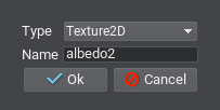
-
Add the second albedo texture to parameters, so that either of them could be assigned. To do this, click + in the Parameters section, then in the dialog box for Type choose Texture2D, in Name enter the name of the new texture – albedo2, and click Ok.添加第二个反照率纹理参数以便随时指定:点击Parameters(参数)区域的 + 按钮,然后在Type(类型)的对话框中选择Texture2D,在Name(名称)栏输入新纹理名称 albedo2,最后点击Ok。
- To use the new parameter in the graph as a node just drag it to the working space.将新参数作为节点拖入工作区。
- Drag the Texture2D node output, type Sample Texture in the constructor panel and press Enter.拖拽 Texture2D节点输出端,在构造器面板输入 Sample Texture 并按回车 Enter。
- Drag the UV input of the Sample Texture node, type in Vertex UV0 and select the corresponding node from the list.将 Sample Texture 节点的 UV 输入端连接至 Vertex UV0 节点。
- Add the Lerp node that will perform linear interpolation between the colors of the albedo1 and albedo2 textures with a coefficient from the mask. Connect the Color output of the Sample Texture node taking the value from albedo1 to input A, and the Color output from the Sample Texture node connected to albedo2 — to input B.添加Lerp节点,该节点将使用遮罩系数对albedo1和albedo2纹理的颜色进行线性插值。将来自albedo1的Sample Texture节点的Color输出连接到输入A,将连接到albedo2的Sample Texture节点的Color输出连接到输入B。
-
And the last item to be added is the interporation coefficient. Create the Surface Custom Texture node and add the Sample Texture node for it (as we already did by connecting Vertex UV0 to the UV input). Drag the Color output from this node to the Coefficient input of the Lerp node and select the X,X,X,X adapter because we need only the first channel.最后需要添加的是插值系数。创建Surface Custom Texture节点并为其添加Sample Texture节点(按照之前连接Vertex UV0到UV输入的方式操作)。将该节点的Color输出拖拽至Lerp节点的Coefficient输入,并选择X,X,X,X适配器,因为我们只需要第一个通道。
-
The resulting graph should look as follows.最终节点图效果应如图所示。
- Save it by clicking the Save button and close the Material Editor.点击Save按钮后关闭材质编辑器。
- Now let's assign this material to the wall by dragging it directly from the Asset Browser and inherit a user material from it by clicking Create a child material in order to assign your own textures.将材质从资源浏览器直接拖拽指定给墙面,并通过点击Create a child material(创建子材质)继承用户材质来分配自有纹理。
-
Download and drag the following images to the Asset Browser, after importing drag wall_brick.jpg and wall_plaster.jpg to the Albedo1 and Albedo2 fields accordingly.下载并将以下图片拖拽至资源浏览器,导入完成后将wall_brick.jpg和wall_plaster.jpg分别拖拽至Albedo1和Albedo2对应字段。


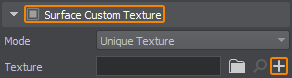
Now we need to determine areas where the brick will show through under the plaster. To do this, select the wall and turn on Surface Custom Texture in the Surfaces section of the Parameters window. In the Texture field, first try to assign the standard textures: white.texture and black.texture. You will notice that in one case the wall is completely plastered, and in the second case it a solid brick wall. Now let's create our own mask for this surface — click + to add a new texture.现在需要确定砖纹的显现区域。选择墙面并在参数窗口的Surfaces部分启用Surface Custom Texture。在Texture字段中,先尝试分配标准纹理:white.texture, 然后 black.texture,可观察到墙面完全粉刷或完全砖纹的效果。接着创建自定义遮罩:点击 + 添加新纹理。
Set the required size, select R (single-channel mask) in Channels, click OK, and write wall_mask as the new texture name.设置所需尺寸,在Channels中选择R(单通道遮罩),点击OK并命名新纹理为wall_mask。
In the next section, we'll learn how to draw the mask directly on the object using the brush to mark the areas where we want to see brickwork. To do this, UNIGINE we'll use the Texture Editor tool.下一节我们将学习使用笔刷直接在物体上绘制遮罩,通过Texture Editor工具标记需要显现砖纹的区域。
本页面上的信息适用于 UNIGINE 2.20 SDK.